|
 |
Semiconductor Devices |
 |
|
|

 |
Silicon
Unidirectional Switches (SUS) KU121
|
 |
Purpose:
Silicon Unidirectional Switches (SUS) KU121 can be applied in phase power regulators, thyristor actuators, inverters, threshold devices, working at half-wave voltage, and other control devices.
The device provides reliable start-up of all types thyristors.
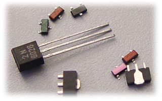
The device is produced in different constructive variants: in package SOT23, TO-92 and in impackaged chip variant with aluminum or soldering pads for surface mounting on hybrid chips plate, as well as other variants.
|
|
 |
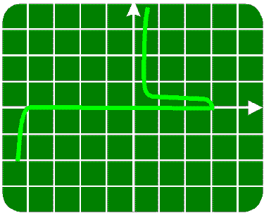
VA-characteristic
KU121B
X - 5V/div
Y- 0,1mA/div
 |
|
|
|
 |
|
|
Constructive Variants SUS
|
|
 |
| Symbol |
Chip
KU121*-5 |
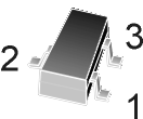
Case SOT-23
KU121*-9 |
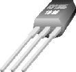
Case TO-92
KU121* |
 |
 KU121-5 |

KU121-9
1- A, 2- G, 3- C |
 3 2 1
KU121
1- G, 2- C, 3- A |
|
|
 |
|
|
Maximum Ratings (TJ=25°C
unless otherwise noted)
|
|
 |
Ratings |
Symbol |
Value |
Unit |
| DC Forward Current |
IF |
200 |
mA |
Repetitive Peak Forward Current
(1% Duti Cycle, 10ms Pulse Width, TA=100°C) |
IFM |
2
|
A |
| DC Gate Current |
IG |
5 |
mA |
| Operating Junction Temperature Range |
TJ |
- 55 to +125 |
°C |
| Power Dissipation KU121*, KU121*-5
KU121*-9 |
PD |
500
250 |
mW |
|
|
 |
|
|
Thermal Characteristics
|
|
 |
Characteristic |
Symbol |
Max |
Unit |
Thermal Resistance, Junction to Ambient
KU121*
KU121*-9 |
RJA |
200
600 |
°C/W |
Thermal Resistance, Junction to Case
KU121*
KU121*-9 |
RJC |
100
260 |
°C/W |
|
|
 |
|
|
Electrical Characteristics*
(T=25°C)
|
|
 |
Parameter |
Symbol |
Min |
Typ |
Max |
Unit |
| Switching Voltage KU121A
KU121B
KU121C |
VS |
6
12
18 |
7,5
14
21 |
9
16
24 |
V |
| Switching Current |
IS |
30 |
50 |
100 |
µA |
| Peak Repetitive Reverse Voltage |
VRRM |
30 |
- |
- |
V |
Forward On-State Voltage
(IF=200mA) |
VF |
- |
- |
1,7 |
V |
| Off State Blocking Current |
IB |
- |
- |
1 |
µA |
|
|
 |
|
|
* Before order the complementary parameters must
defined more precisely.
|


|


